
With the rapid development of the global photovoltaic industry, the number of retired modules continues to increase. Traditional chemical processing methods suffer from issues such as secondary pollution and low efficiency. In contrast, PV pyrolysis technology is becoming the top choice due to its advantages of non-corrosive operation, low emissions, and high-value recovery. The pyrolysis process involves controlling temperature, atmosphere, and heating rate to decompose and volatilize the encapsulation film. Thus, it is easy to remove glass, wafferi silicon, and metal wires in order to achieve resource recovery.
Do different encapsulation films have the same pyrolysis temperature?
Photovoltaic modules have various encapsulation film types, such as EVA, POE, and PVB in common. They play a crucial role in photovoltaic encapsulation by providing adhesion, waterproofing, and UV protection, while also being the most challenging component to remove during the solar panel recycling. In PV pyrolysis technology, the pyrolysis temperature relates to the type and thickness of the adhesive film as well as the laminate structure.


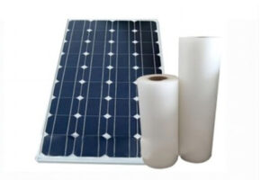
Ethylene-vinyl acetate copolymer is currently the most widely used encapsulation material. Its pyrolysis initiation temperature is typically around 350°C, with a decomposition range of approximately 350–500°C. Pyrolysis releases small amounts of acetic acid and organic volatiles, so the temperature control and tail gas purification are critical.
POE film uses polyolefin as its base material, and its thermal stability is higher than that of EVA. Its decomposition temperature typically ranges between 420–550°C, and the pyrolysis rate is relatively gentle which is more suitable for continuous processes. POE components leave minimal colloidal residue at high temperatures, and the wafer surface remains cleaner.
It is mainly for double-glass modules and has low heat resistance, which usually begins to decompose at 280–420°C. PVB has a low softening point, which allows for low-energy removal through a combination of thermal softening and pyrolysis.
Certain new modules employ multi-layer encapsulation with a broader pyrolysis temperature range, which requires segmental heating. The initial heating stage removes the binder, while the subsequent stage completely decomposes organic matter.
How to choose between continuous and batch PV pyrolysis technology?
One of the most common questions that customers ask when learning about our datrysiad prosiect pyrolysis paneli solar is: “Is your equipment continuous or batch? Which is better?” In fact, both processes have their respective applications, and the choice depends on the scale of treatment, operational frequency, and investment budget.

The batch pyrolysis process features a simple structure and flexible operation, which is especially suitable for treating small-to-medium scale or multi-type modules. It operates through a process sequence of loading, heating, pyrolysis, cooling, and discharging, with each batch completed independently.
Its process adaptability is strong, and it can flexibly adjust the temperature curve for different component materials. The cost peiriant ailgylchu paneli solar is relatively low, and maintenance and cleaning are also quite convenient. Given that the intermittent pyrolysis process still has room for further optimization in terms of production capacity and energy consumption, you can choose to enhance overall efficiency and energy performance through complementary equipment.

The continuous pyrolysis process achieves uninterrupted operation through the continuous feeding and discharge of materials, which is suitable for large-scale and industrial production. Its primary advantage lies in 24 hour continuous production capability. High thermal energy utilization efficiency enables synergistic operation with waste heat recovery systems to reduce energy consumption, while advanced automation levels minimize labor requirements.
Ar yr un pryd, this process demands higher construction investment and material feeding uniformity, and the commissioning period is longer. Felly, we will fully plan and optimize during the design and implementation phases.
How to Select the Optimal Photovoltaic Panel Pyrolysis Solution Based on Production Capacity and Investment?
YUSHUNXIN has been developing Technoleg ailgylchu PV for many years and possesses mature rheoli ailgylchu paneli solar.
Controlled thermal delamination
Use when laminate release requires a controlled thermal duty integrated with gas treatment and solid separation.
Incoming material
Module construction, encapsulant, contamination, feed preparation and operating continuity.
Expected outputs
Thermally released and classified material fractions; condensable/non-condensable streams remain project-specific.
Project interfaces
Reactor/tunnel duty, secondary combustion, gas cleaning, cooling, amddiffyn rhag tân, monitoring and residues.
Use only the row matching the selected process boundary.
| Catalogue reference | Gallu | Grym | Physical envelope | Included boundary |
|---|---|---|---|---|
| YSX-TK500Tunnel thermal | 500 kg/awr | 116.65 kW | 65 × 13 × 7.5 m | Continuous tunnel thermal line |
| YSX-TK1000Tunnel thermal | 1,000 kg/awr | 126.65 kW | 72 × 13 × 7.5 m | Continuous tunnel thermal line |
| YSX-TK2000Tunnel thermal | 2,000 kg/awr | 136.65 kW | 80 × 13 × 7.5 m | Continuous tunnel thermal line |
| YSX-PF5Batch thermal | 5 t/diwrnod | 140.45 kW | 46 × 33 × 7.5 m | Mixed-module batch thermal line |
| YSX-PF16Batch thermal | 16 t/diwrnod | 142.45 kW | 40 × 26 × 7.5 m | Mixed-module batch thermal line |
| YSX-8000Earlier integrated thermal | 8 t/diwrnod | Configuration controlled | 50 × 30 × 8 m | Earlier thermal project reference; reactor Φ2200 × 6000 × 20 mm |
| YSX-16000Earlier integrated thermal | 16 t/diwrnod | Configuration controlled | 60 × 30 × 8 m | Earlier thermal project reference; reactor Φ2800 × 6600 × 18 mm |
Configuration rule: catalogue capacity is a planning reference. Stable throughput, installed/operating power, footprint, recovery, purity, emissions and utility demand require the approved equipment list, representative material and written acceptance conditions.
Information required before configuration and quotation
- Representative material photos, specifications and available sample.
- Required capacity plus hours per shift, shifts per day and operating days.
- Allbynnau targed, sampling method and downstream receiver requirements.
- Site country, available power, fuel, dwr, compressed air and building limits.
- Local environmental, fire, storage and occupational-safety requirements.
- Requested delivery boundary: offer, gosodiad, installation, commissioning and training.


